TUSPIPE’s API 5L X56 line pipes fully comply with API standards, and the manufactured steel pipes undergo rigorous process inspections. The API 5L X56 rating is suitable for transport projects requiring higher pressure resistance, providing customers with robust and durable solutions.
API 5L X56
API 5L standard covers steel pipes for use in conveying oil, gas, water, and other liquids at various temperatures and pressures. API 5L X56 steel grade is used in the production of different kinds of steel pipe, including ERW steel pipe, seamless steel pipe, LSAW steel pipe, and SSAW steel pipe. API 5L X56 material is a steel grade with improved mechanical properties and strength. It is typically used in the production of steel pipe for use in the transportation of petroleum and natural gas. The increased strength of this steel grade makes it ideal for use in high-pressure applications. X56 material is available in two different grades: PSL-1 and PSL-2. PSL-1 is the most commonly used grade, while PSL-2 is typically used in higher-pressure applications.
Instituto Americano del Petróleo‘s API 5L specification is for line pipes used in pipelines for transporting oil, natural gas, and water. The specification covers two types of line pipes: welded and seamless. Welded line pipes are made by joining together sections of pipe using welding techniques, while seamless line pipes are made from a single piece of pipe. Both types of line pipes must meet certain requirements to be certified by the API. For example, they must be able to withstand the high pressures and temperatures that are common in pipeline applications. In addition, they must be resistant to corrosion and have a minimum wall thickness. The API 5L specification is an important standard document that guides manufacturers of line pipes used in pipelines.
Desde 1998, Tianjin United Steel Piping Co., Ltd (TUSPIPE) se ha comprometido a suministrar tubos de línea de alta calidad.
Con más de 500.000 toneladas de capacidad de producción anual, la empresa presta servicio a diversos campos e industrias, como la explotación y transmisión de petróleo y gas, la construcción naval y de automóviles, el agua y la electricidad, la protección del medio ambiente, la ingeniería mecánica, la construcción de infraestructuras, etc.
TUSPIPE da mucha importancia a la calidad de los productos y a un riguroso control de calidad de los mismos. Para mantener la buena calidad de los productos, la empresa ha establecido un Centro de Pruebas e Inspección desde 2004. Con una serie de pruebas de última generación y equipos de inspección, el centro de pruebas e inspección es capaz de realizar las pruebas de tracción, pruebas hidráulicas, pruebas de impacto, DWTT, etc.
API 5L X56 line pipe is a common grade pipe for the transportation of petroleum, oil and gas. It is also referred to as L390 pipe, which refers to its minimum yield strength in PSI (pounds per square inch). In addition to the transportation of petroleum, oil and gas, API 5L X56 line pipe is also used in the construction industry for applications such as piling jobs. The durability and flexibility of API 5L X56 line pipe make it an ideal choice for a variety of applications.
API 5L X56 Pipe Chemical Composition
- Chemical Composition for API 5L X56 PSL 1 pipe with t ≤ 0.984”
Grado de acero
API 5L X56 Mass fraction, % based on heat and product analyses a,g
C
Mn
P
S
V
Nb
Ti
max b
max b
max
max
max
max
max
Tubos soldados
X56
0.26
1.4
0.3
0.3
d
d
d
a. Cu ≤ = 0,50% Ni; ≤ 0,50%; Cr ≤ 0,50%; y Mo ≤ 0,15%, b. Por cada reducción de 0,01% por debajo de la concentración máxima especificada para el carbono, se permite un aumento de 0,05% por encima de la concentración máxima especificada para el Mn, hasta un máximo de 1,65% para los grados ≥ L245 o B, pero ≤ L360 o X52; hasta un máximo de 1,75% para los grados > L360 o X52, pero < L485 o X70; y hasta un máximo de 2,00% para el grado L485 o X70.", c. Salvo acuerdo en contrario NB + V ≤ 0,06%, d. Nb + V + TI ≤ 0,15%, e. Salvo acuerdo en contrario ., f. Salvo acuerdo en contrario, NB + V = Ti ≤ 0,15%, g. No se permite la adición deliberada de B y el residuo B ≤ 0,001%
- Chemical Composition for API 5L X56 PSL 2 Pipe with t ≤ 0.984”
Grado de acero
API 5L X56 Mass fraction, % based on heat and product analyses
Carbono Equiv a
C
Si
Mn
P
S
V
Nb
Ti
Otros
CE IIW
CE Pcm
max b
max
max b
max
max
max
max
max
max
max
Tubos soldados
X56M
0.22
0.45
1.3
0.025
0.015
0.05
0.05
0.04
e,l
0.43
0.25
a. SMLS t>0,787”, los límites CE serán los acordados. Se aplicarán los límites CEIIW si C > 0,12% y los límites CEPcm si C ≤ 0,12%, b. Por cada reducción de 0,01% por debajo del máximo especificado para C, se admite un aumento de 0,05% por encima del máximo especificado para Mn, hasta un máximo de 1,65% para los grados ≥ L245 o B, pero ≤ L360 o X52; hasta un máximo de 1.75% para los grados > L360 o X52, pero L555 o X80., c. Salvo acuerdo en contrario Nb = V ≤ 0,06%, d. Nb = V = Ti ≤ 0,15%, e. Salvo acuerdo en contrario, Cu ≤ 0,50%; Ni ≤ 0,30% Cr ≤ 0,30% y Mo ≤ 0,15%, f. Salvo acuerdo en contrario, g. Salvo acuerdo en contrario, Nb + V + Ti ≤ 0,15%, h. Salvo acuerdo en contrario, Cu ≤ 0,50% Ni ≤ 0,50% Cr ≤ 0,50% y MO ≤ 0,50%, i. Salvo acuerdo en contrario, Cu ≤ 0,50% Ni ≤ 1,00% Cr ≤ 0,50% y MO ≤ 0,50%, j. B ≤ 0,004%, k. Salvo acuerdo en contrario, Cu ≤ 0,50% Ni ≤ 1,00% Cr ≤ 0,55%, y MO ≤ 0,80%, l. Para todas las calidades de tubos PSL 2, excepto las calidades con notas al pie j señaladas, se aplica lo siguiente. Salvo acuerdo en contrario, no se permite ninguna adición intencionada de B y el B residual ≤ 0,001%.
API 5L X56 Pipe Mechanical Properties
- Mechanical Properties for API 5L X56 PSL-1 Pipe
Grado de la tubería
Propiedades de tracción - Cuerpo de tubo de SMLS y tubos soldados PSL 1
Costura de tubería soldada
límite elástico a
Resistencia a la tracción a
Alargamiento
Resistencia a la tracción b
Rt0,5 PSI Mín
Rm PSI Mín
(en 2in Af % min)
Rm PSI Mín
X56
65,300
77,500
c
77,500
a. Para el grado intermedio, la diferencia entre la resistencia a la tracción mínima especificada y el límite elástico mínimo especificado para el cuerpo del tubo será la indicada para el grado inmediatamente superior.
b. Para las calidades intermedias, la resistencia mínima a la tracción especificada para el cordón de soldadura será la misma que la determinada para la carrocería utilizando la nota a.
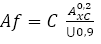
c. El alargamiento mínimo especificado, Af, expresado en porcentaje y redondeado al porcentaje más próximo, se determinará utilizando la siguiente ecuación:
Donde C es 1 940 para el cálculo con unidades Si y 625 000 para el cálculo con unidades USC.
Axc es el área de la sección transversal de la probeta de tracción aplicable, expresada en milímetros cuadrados (pulgadas cuadradas), como sigue
- Para las probetas de sección circular, 130 mm2 (0,20 pulg2) para las probetas de 12,7 mm (0,500 pulg) y 8,9 mm (,350 pulg) de diámetro; y 65 mm2 (0,10 pulg2) para las probetas de 6,4 mm (0,250 pulg) de diámetro.
- Para las probetas de sección completa, la menor de a) 485 mm2 (0,75 pulg2) y b) el área de la sección transversal de la probeta, derivada utilizando el diámetro exterior especificado y el espesor de pared especificado de la tubería, redondeada a los 10 mm2 (0,10 pulg2) más próximos.
- Para las probetas en tiras, la menor de a) 485 mm2 (0,75 pulgadas2) y b) el área de la sección transversal de la probeta, obtenida utilizando la anchura especificada de la probeta y el espesor de pared especificado de la tubería, redondeada a los 10 mm2 (0,10 pulgadas2) más próximos.
U es la resistencia mínima a la tracción especificada, expresada en megapascales (libras por pulgada cuadrada)
- Mechanical Properties for API 5L X56 PSL-2 Pipe
Grado de la tubería
Propiedades de tracción - Cuerpo de tubo de SMLS y tubos soldados PSL 2
Costura de tubería soldada
límite elástico a
Resistencia a la tracción a
Relación a, c
Alargamiento
Resistencia a la tracción d
Rt0,5 PSI Mín
Rm PSI Mín
R10,5IRm
(en 2in)
Rm (psi)
Af %
Mínimo
Máximo
Mínimo
Máximo
Máximo
Mínimo
Mínimo
X56N, X56Q, X56M
56,600
79,000
71,100
110,200
0.93
f
71,100
a. Para el grado intermedio, consulte la especificación completa API5L.
b. para los grados > X90 se refiere a la especificación API5L completa.
c. Este límite se aplica a las tartas con D> 12,750 pulg.
d. Para los grados intermedios, la resistencia a la tracción mínima especificada para el cordón de soldadura será el mismo valor que se determinó para el cuerpo del tubo utilizando el pie a.
e. para las tuberías que requieran ensayos longitudinales, el límite elástico máximo será ≤ 71.800 psi
f. El alargamiento mínimo especificado, Af, expresado en porcentaje y redondeado al porcentaje más próximo, se determinará utilizando la siguiente ecuación:
Donde C es 1 940 para el cálculo con unidades Si y 625 000 para el cálculo con unidades USC.
Axc es el área de la sección transversal de la probeta de tracción aplicable, expresada en milímetros cuadrados (pulgadas cuadradas), como sigue
- Para las probetas de sección circular, 130 mm2 (0,20 pulg2) para las probetas de 12,7 mm (0,500 pulg) y 8,9 mm (,350 pulg) de diámetro; y 65 mm2 (0,10 pulg2) para las probetas de 6,4 mm (0,250 pulg) de diámetro.
- Para las probetas de sección completa, la menor de a) 485 mm2 (0,75 pulg2) y b) el área de la sección transversal de la probeta, derivada utilizando el diámetro exterior especificado y el espesor de pared especificado de la tubería, redondeada a los 10 mm2 (0,10 pulg2) más próximos.
- Para las probetas en tiras, la menor de a) 485 mm2 (0,75 pulgadas2) y b) el área de la sección transversal de la probeta, obtenida utilizando la anchura especificada de la probeta y el espesor de pared especificado de la tubería, redondeada a los 10 mm2 (0,10 pulgadas2) más próximos.
U es la resistencia mínima a la tracción especificada, expresada en megapascales (libras por pulgada cuadrada).
g. Valores inferiores a R10,5IRm pueden ser especificados por acuerdo.
h. para grados > x90 se refiere a la especificación API5L completa.
Dimensions and Sizes of API 5L X56 Line Pipe
When choosing an API 5L X56 line pipe, it is important to check the diameter and size of the pipe to ensure that it meets the required standards. The dimensions and masses of API 5L line pipes are specified in ISO 4200 and ASME B36.10M. These standards provide a guide for different size pipes and specify the wall thickness of each size. To check if a particular pipe meets the required standards, refer to these tables. Doing so will help ensure that the pipe is the right size and has the correct wall thickness. By following these guidelines, you can be sure that your API 5L line pipe will meet the necessary requirements.
NPS
O. D.
W. T.
DN
En pulgadas
mm
SCH5S
SCH10S
SCH10
SCH20
SCH30
SCH40
SCH60
SCH80
SCH100
SCH120
SCH140
SCH160
Sth
XS
XXS
50
2″
60.3
1.65
2.77
-
-
-
3.91
-
5.54
-
-
-
8.74
3.91
5.54
11.07
65
2 1/2″
73
2.11
3.05
-
-
-
5.16
-
7.01
-
-
-
9.53
5.16
7.01
14.02
80
3″
88.9
2.11
3.05
-
-
-
5.49
-
7.62
-
-
-
11.13
5.49
7.52
15.24
90
3 1/2″
101.6
2.11
3.05
-
-
-
5.74
-
8.08
-
-
-
-
5.74
8.08
-
100
4″
114.3
2.11
3.05
-
-
-
6.02
-
8.58
-
11.13
-
13.49
6.02
8.56
17.12
125
5″
141.3
2.77
3.4
-
-
-
6.55
-
9.53
-
12.7
-
15.88
6.55
9.53
18.05
150
6″
168.3
2.77
3.4
-
-
-
7.11
-
10.97
-
14.27
-
18.26
7.11
10.97
21.95
200
8″
219.1
2.77
3.76
-
6.35
7.04
8.18
10.31
12.7
15.09
18.26
20.62
23.01
8.18
12.7
22.23
250
10″
273.1
3.4
4.19
-
6.35
7.8
9.27
12.7
15.09
18.26
21.44
25.4
28.58
9.27
12.7
25.4
300
12″
323.9
3.96
4.57
-
6.35
8.38
10.31
14.27
17.48
21.44
25.4
28.58
33.32
9.53
12.7
25.4
350
14″
355.5
3.96
4.78
6.35
7.92
9.53
11.13
15.09
19.05
23.83
27.79
31.75
35.71
9.53
12.7
-
400
16″
406.4
4.19
4.78
6.35
7.92
9.53
12.7
16.66
21.44
26.19
30.96
36.53
40.49
9.53
12.7
-
450
18″
457.2
4.19
4.78
6.35
7.92
11.13
14.27
19.05
23.83
39.36
34.93
39.67
45.24
-
-
-
500
20″
508
4.78
5.54
6.35
9.53
12.7
15.09
20.62
26.19
32.54
38.1
44.45
50.01
-
-
-
550
22″
558.8
4.78
5.54
6.35
9.53
12.7
-
22.23
28.58
34.93
41.28
47.63
53.98
-
-
-
600
24″
609.6
5.54
6.35
6.35
9.53
14.27
17.48
24.61
30.96
38.89
46.02
52.37
59.54
-
-
-
API 5L X56 Pipe Tolerance
Tolerancia O.D.
Tolerancia W.T.
X56
D < 60,3 mm
+0,41/-0,40 mm
D < 73mm
+15%/-12.5%
D ≥ 60,3 m
+0,75/-0,40 mm
D ≥ 73mm
+15%/-12.5%
Test and inspection of API 5L X56 Line pipes
- Prueba hidrostática
Hydrostatic testing is a key quality control step during the production of API 5L line pipe. The hydro-test involves filling the pipe with water and then subjecting it to pressure to check for leaks. During the test, special attention is paid to the weld seam, as this is the weakest point in the pipe body. The hydro-test is an important way to ensure that the steel pipe meets the required standards for strength and durability. Hydrostatic testing is a key quality control step during the production of API 5L line pipe. The hydro-test involves filling the pipe with water and then subjecting it to pressure to check for leaks. During the test, special attention is paid to the weld seam, as this is the weakest point in the pipe body. The hydro-test is an important way to ensure that the steel pipe meets the required standards for strength and durability. Hydrostatic testing is a key quality control step during the production of steel line pipe for API 5L – which specifies requirements for the manufacture of line pipe used in conveying oil, gas, and water in petroleum industries.
- Bending Test
The bending test is an essential test during API 5L line pipe production. It is mainly to check if there is any crack on the welding seam of the line pipe. The crack is then inspected to see if it meets the requirements for API 5L line pipe production. If the crack does not meet the requirements, the pipe is rejected and a new sample is taken. This test is very important because welding seam crack will cause oil or gas leakage during transportation.
- Prueba de aplanamiento
The flattening test is performed during the production of the API 5L line pipe. The purpose of the test is to check for any cracks in the steel pipe or welds. A sample of the pipe is placed on a flattening machine, and a wheel is rolled over it to deform the material. The deformation is then measured along both the longitudinal and circumferential axes. The results of the test are used to determine the quality of the pipe and ensure that it meets all safety requirements.
- Prueba de impacto CVN
The impact test is a mandatory test during the production of steel pipes according to the API 5L specification. The test is conducted on three different positions of the steel pipe: the pipe body, the welding seam, and the heat-affected zone. The purpose of the impact test is to check the Charpy V-Notch (CVN) values of the steel in these three positions. The CVN values are important indicators of the steel’s toughness and resistance to brittle fracture. The impact test is usually conducted at a temperature of -20°C (-4°F).
- DWT Test for PSL-2 Welded Pipe
In the oil and gas industry, large diameter steel pipe is used for a variety of applications, such as transporting crude oil and natural gas. To ensure that these pipes meet the required standards, they must undergo several tests, including the DWTT test. DWTT stands for Drop-Weight Tear Test, and it is used to assess a pipe’s fracture toughness. The test involves dropping a weight onto the pipe, which causes it to fracture. The resulting fracture is then examined to determine the amount of energy required to cause the break. This information is then used to assess the pipe’s suitability for use in high-pressure applications. The DWTT test is just one of many tests that are conducted on large diameter steel pipes during the production process.
OCTG
Liner ranurado
Fabricación de acero
Accesorios de tubería
Scroll al inicio
Obtenga un presupuesto ahora
Rellene el siguiente formulario y nuestro equipo estará encantado de atenderle