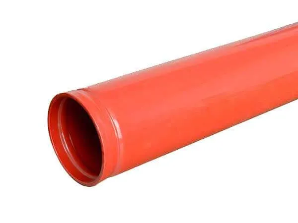
EN 10255
TUSPIPE strictly adheres to the EN 10255 standard in its steel pipe production process. Our meticulously designed EN 10255 steel pipes meet a wide range of customer needs, providing you with high-precision EN 10255 steel pipes.
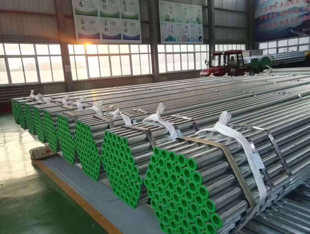
EN 10255
Les EN 10255 standard is a European standard that helps to ensure the safety and quality of non-alloy steel tubes that are welded or threaded. This standard includes a variety of choices for finishing tube ends and coatings, which helps to protect the tubing from damage during transport and use. The EN 10255 standard also specifies the minimum wall thickness for each type of tubing, which helps to prevent weak or damaged tubing from being used in construction projects. In addition, the tubes shall be manufactured by a seamless (S) or longitudinally welded (W) process. By following this standard, manufacturers can help to ensure that their products meet the highest quality standards.
Pourquoi choisir tuspipe ?

Depuis 1998, Tianjin United Steel Piping Co., Ltd (TUSPIPE) s'engage à fournir des tubes de canalisation de haute qualité.
Avec une capacité de production annuelle de plus de 500 000 tonnes, l'entreprise dessert divers domaines et industries, tels que l'exploitation et la transmission du pétrole et du gaz, la construction navale et automobile, l'eau et l'électricité, la protection de l'environnement, l'ingénierie mécanique, la construction d'infrastructures, etc.
TUSPIPE accorde une grande importance à la qualité des produits et à leur contrôle rigoureux. Afin de maintenir une bonne qualité des produits, l'entreprise a mis en place un centre d'essai et d'inspection depuis 2004. Doté d'une série d'équipements d'essai et d'inspection de pointe, le centre d'essai et d'inspection est en mesure d'effectuer des essais de traction, des essais hydrauliques, des essais d'impact, des essais DWTT, etc.
Steel Grades of EN 10255 Pipes
Dimensions and Sizes of EN 10255 Steel Pipes
The following table contains the dimensions and weight of steel tubes in accordance with the European standard EN 10255 “Non-Alloy Steel Tubes Suitable for Welding and Threading” and British Standard BS 1387:1985 “Specification for screwed and socketed steel tubes and tubulars, and for plain end steel tubes suitable for welding or screwing to BS 21 pipe threads”:
| Nominal Bore | Diamètre extérieur | Épaisseur | Poids | ||||||
|---|---|---|---|---|---|---|---|---|---|
| Light | Medium/ Heavy | Light | Moyen | Lourd | Light | Moyen | Lourd | ||
| Pouce | mm | mm | mm | mm | mm | mm | kg/m | kg/m | kg/m |
| 1/4 | 8 | 13.6 | 13.9 | 1.8 | 2.3 | 2.9 | 0.515 | 0.641 | 0.765 |
| 3/8 | 10 | 17.1 | 17.4 | 1.8 | 2.3 | 2.9 | 0.67 | 0.839 | 1.02 |
| 1/2 | 15 | 21.4 | 21.7 | 2 | 2.6 | 3.2 | 0.947 | 1.21 | 1.44 |
| 3/4 | 20 | 26.9 | 27.2 | 2.3 | 2.6 | 3.2 | 1.38 | 1.56 | 1.87 |
| 1 | 25 | 33.8 | 34.2 | 2.6 | 3.2 | 4 | 1.98 | 2.41 | 2.94 |
| 1 1/4 | 32 | 42.5 | 42.9 | 2.6 | 3.2 | 4 | 2.54 | 3.1 | 3.8 |
| 1 1/2 | 40 | 48.4 | 48.8 | 2.9 | 3.2 | 4 | 3.23 | 3.57 | 4.38 |
| 2 | 50 | 60.2 | 60.8 | 2.9 | 3.6 | 4.5 | 4.08 | 5.03 | 6.19 |
| 2 1/2 | 65 | 76 | 76.6 | 3.2 | 3.6 | 4.5 | 5.71 | 6.43 | 7.93 |
| 3 | 80 | 88.7 | 89.5 | 3.2 | 4 | 5 | 6.72 | 8.37 | 10.3 |
| 4 | 100 | 113.9 | 114.9 | 3.6 | 4.5 | 5.4 | 9.75 | 12.2 | 14.5 |
| 5 | 125 | - | 140.6 | - | 5 | 5.4 | - | 16.6 | 17.9 |
| 6 | 150 | - | 165.1 | - | 5 | 5.4 | - | 19.7 | 21.3 |
Chemical Composition of EN 10255 Pipes
| Grade | Chemical composition (%) | |||
|---|---|---|---|---|
| S195T | C | Mn | P | S |
| ≤ 0.20 | ≤ 1.40 | ≤ 0.035 | ≤ 0.030 | |
Mechanical Properties of EN 10255 Pipes
| Grade | Propriétés mécaniques | ||
|---|---|---|---|
| S195T | Limite d'élasticité (Mpa) | Résistance à la traction (Mpa) | Élongation (%) |
| 195 | 320-520 | 20 | |
Tolerances of EN 10255 Piping
- Type L - Tolérance dimensionnelle et masse unitaire
| Diamètre extérieur spécifié a D | Désignation du fil a R | Diamètre extérieur | Épaisseur de la paroi T | Masse par unité de longueur du tube nu | ||
|---|---|---|---|---|---|---|
| max. | min. | Extrémité lisse | Fileté et à emboîtement | |||
| (mm) | - | (mm) | (mm) | (mm) | (kg/m) | (kg/m) |
| 13.5 | 1/4 | 13.9 | 13.2 | 2.0 | 0.567 | 0.571 |
| 17.2 | 3/8 | 17.4 | 16.7 | 2.0 | 0.750 | 0.756 |
| 21.3 | 1/2 | 21,7 | 21.0 | 2.3 | 1.08 | 1.09 |
| 26.9 | 3/4 | 27.1 | 26.4 | 2.3 | 1.40 | 1.41 |
| 33.7 | 1 | 34.0 | 33.2 | 2.9 | 2.20 | 2.22 |
| 42.4 | 1 1/4 | 42.7 | 41.9 | 2.9 | 2.82 | 2.85 |
| 48.3 | 1 1/2 | 48.6 | 47.8 | 2.9 | 3.25 | 3.29 |
| 60.3 | 2 | 60.7 | 59.6 | 3.2 | 4.51 | 4.58 |
| 76.1 | 2 1/2 | 76.0 | 75.2 | 3.2 | 5.75 | 5.87 |
| 88.9 | 3 | 88.7 | 87.9 | 3.2 | 6.76 | 6.93 |
| 101.6 | 3 1/2 | 101.2 | 100.3 | 3.6 | 8.7 | 8.88 |
| 114.3 | 4 | 113.9 | 113.0 | 3.6 | 9.83 | 10.1 |
| 139.7 | 5 | 140.8 | 138.5 | 4.5 | 15.0 | 15.5 |
| 165.1 | 6 | 166.5 | 163.9 | 4.5 | 17.8 | 18.4 |
| a Pour la relation entre le diamètre extérieur spécifié (D), la taille du filetage (R) et le diamètre nominal (DN), voir l'annexe A. T = épaisseur de paroi spécifiée. | ||||||
- Type L1 - Tolérance dimensionnelle et masse unitaire
| Diamètre extérieur spécifié a D | Désignation du fil a R | Diamètre extérieur | Épaisseur de la paroi T | Masse par unité de longueur du tube nu | ||
|---|---|---|---|---|---|---|
| max. | min. | Extrémité lisse | Fileté et à emboîtement | |||
| (mm) | - | (mm) | (mm) | (mm) | (kg/m) | (kg/m) |
| 13.5 | 1/4 | 13.9 | 13.2 | 2.0 | 0.570 | 0.574 |
| 17.2 | 3/8 | 17.4 | 16.7 | 2.0 | 0.742 | 0.748 |
| 21.3 | 1/2 | 21,7 | 21.0 | 2.3 | 1.08 | 1.09 |
| 26.9 | 3/4 | 27.1 | 26.4 | 2.3 | 1.39 | 1.40 |
| 33.7 | 1 | 34.0 | 33.2 | 2.9 | 2.20 | 2.22 |
| 42.4 | 1 1/4 | 42.7 | 41.9 | 2.9 | 2.82 | 2.85 |
| 48.3 | 1 1/2 | 48.6 | 47.8 | 2.9 | 3.24 | 3.28 |
| 60.3 | 2 | 60.7 | 59.6 | 3.2 | 4.49 | 4.56 |
| 76.1 | 2 1/2 | 76.3 | 75.2 | 3.2 | 5.73 | 5.85 |
| 88.9 | 3 | 89.4 | 87.9 | 3.6 | 7.55 | 7.72 |
| 114.3 | 4 | 114.9 | 113.0 | 4.0 | 10.8 | 11.1 |
| a Pour la relation entre le diamètre extérieur spécifié (D), la taille du filetage (R) et le diamètre nominal (DN), voir l'annexe A. T = épaisseur de paroi spécifiée. | ||||||
- Type L2 - Tolérance dimensionnelle et masse unitaire
| Diamètre extérieur spécifié a D | Désignation du fil a R | Diamètre extérieur | Épaisseur de la paroi T | Masse par unité de longueur du tube nu | ||
|---|---|---|---|---|---|---|
| max. | min. | Extrémité lisse | Fileté et à emboîtement | |||
| (mm) | - | (mm) | (mm) | (mm) | (kg/m) | (kg/m) |
| 13.5 | 1/4 | 13.6 | 13.2 | 1.8 | 0.515 | 0.519 |
| 17.2 | 3/8 | 17.1 | 16.7 | 1.8 | 0.670 | 0.676 |
| 21.3 | 1/2 | 21.4 | 21.0 | 2.0 | 0.947 | 0.956 |
| 26.9 | 3/4 | 26.9 | 26.4 | 2.3 | 1.38 | 1.49 |
| 33.7 | 1 | 33.8 | 33.2 | 2.6 | 1.98 | 2.00 |
| 42.4 | 1 1/4 | 42.5 | 41.9 | 2.6 | 2.54 | 2.57 |
| 48.3 | 1 1/2 | 48.4 | 47.8 | 2.9 | 3.23 | 3.27 |
| 60.3 | 2 | 60.2 | 59.6 | 2.9 | 4.08 | 4.15 |
| 76.1 | 2 1/2 | 76.0 | 75.2 | 3.2 | 5.71 | 5.83 |
| 88.9 | 3 | 88.7 | 87.9 | 3.2 | 6.72 | 6.89 |
| 114.3 | 4 | 113.9 | 113.0 | 3.6 | 9.75 | 10.0 |
| a Pour la relation entre le diamètre extérieur spécifié (D), la taille du filetage (R) et le diamètre nominal (DN), voir l'annexe A. T = épaisseur de paroi spécifiée. | ||||||
- Épaisseur de la paroi
- ±10%. pour les séries M et H et le type L ;
- -8% avec la tolérance plus limitée par la tolérance de masse, pour les types L1 et L2.
- Poids
- ±7.5% sur les paquets de 10 tonnes ou plus, pour les séries M et H et le type L ;
- +10%, -8% sur les tubes individuels pour les types L1 et L2.
- Rectitude
La rectitude ne doit pas dépasser 0,002 L.
Test and Inspection of EN 10255 Piping
- Essai de traction
L'essai de traction doit être effectué sur un tube nu conformément à la norme EN 10002-1.
- Test de pliage
In order to ensure the quality of our welded tubes, we perform a bend test in accordance with EN 10232. This test is applied to bare tubes with specified outside diameters of 17.2mm up to and including 60.3mm, and the tube is bent to an angle of 90°. The groove in the forming tool has a width that fits the tube diameter accurately and a depth not less than half of the diameter. The radius at the bottom of the groove of the former is as given in the table below. Welded tubes shall be bent with the weld at the outside of the bend. The tubes shall show no cracks visible without magnifying aids. By performing this test, we can ensure that our welded tubes meet the highest standards of quality.
| Diamètre (mm) | 17.2 | 21.3 | 26.9 | 33.7 | 42.4 | 48.3 | 60.3 |
| Rayon de courbure | 50 | 65 | 85 | 100 | 150 | 170 | 220 |
- Test d'aplatissement
In order to ensure the structural integrity of welded tubes, a flattening test is carried out in accordance with EN 10233. The test is applied to bare tubes with an outside diameter greater than 60.3mm and involves flattening the tube in a press until the distance between platens, measured under load, reaches 75% of the original outside diameter. The weld should be placed alternately at 0 or 90° to the direction of flattening. During the flattening process, the tube should show no cracks or flaws visible without magnifying aids. Once the distance between platens reaches 60% of the original outside diameter, slight premature failure at the edges shall not be considered as a cause for rejection. This test ensures that welded tubes can withstand the required amount of pressure without failing.
- Test d'étanchéité
Any system that involves the transport of fluids must be designed to ensure that there are no leaks. This is especially important in industries like healthcare, where even a small leak can have serious consequences. To ensure the integrity of their products, manufacturers must subject each tube to a leak-tightness test. The most common type of test is a hydrostatic test, which involves filling the tube with water and pressurizing it to 50 bar for at least 5 seconds. However, manufacturers also have the option of using an electromagnetic test in accordance with EN 10246-1. Whichever type of test is used, the goal is to ensure that the finished product is completely safe and fit for use.
- Contrôle dimensionnel
Le contrôle de la taille et des dimensions doit être effectué.
- Examen visuel
L'examen visuel est effectué conformément à la norme.
Marking on EN 10255 Pipes
Les marquages doivent être placés au moins une fois à moins d'un mètre d'une extrémité du tube, et les tubes doivent être marqués avec les informations suivantes par des méthodes appropriées et durables :
- Le nom ou la marque du fabricant ;
- Le symbole de gravité (H ou M) et le type (L, L1 ou L2) ;
- Le symbole du processus de fabrication (S ou W)
Colors can be a helpful way to organize and identify different objects, and this is especially true when it comes to tubes. Tubes are often used in a variety of settings, from construction sites to laboratories, and they come in a wide range of sizes and materials. While each type of tube has its own unique properties, they all need to be marked so that they can be easily identified. The manufacturer may opt to use color coding instead of series or type markings. This will make it easy to quickly identify the different types of tubes, saving time and preventing confusion.
| Lourd | Moyen | Les types |
|---|---|---|
| Rouge | BlueSee | Tolerance Table |
Les informations suivantes figurent sur l'étiquette de chaque botte :
- Le nom ou la marque du fabricant ;
- Le code de la norme EN 10255 ;
- Le symbole du processus de fabrication (S ou W)
- Le D (diamètre extérieur) ou le R (taille du filetage) ;
- La série ou le type ou l'épaisseur de paroi spécifiée.
EN 10255 and BS 1387 comparison table
Abolished and replaced by the European standard EN 10255: 2004 (adopted by the UK national standard body as BS EN 10255:2004 “non-alloy steel tubes suitable for welding or threading”), BS 1387:1985 has been retired. The kinds in BS 1387 and EN 10255 that correspond to each other are listed in the table below.
| EN 10255 L | - |
| EN 10255 L1 | - |
| EN 10255 L2 | BS 1387 Light |
| EN 10255 Medium | BS 1387 Medium |
| EN 10255 Heavy | BS 1387 Heavy |
Appearance of EN 10255 Pipes
The quality of a tube is often determined by its surface finish. For this reason, manufacturers must take care to ensure that their products are free from defects that can be detected by visual examination. The internal and external surfaces of the tube must be smooth, with no imperfections or marks that would require dressing. Any surface imperfections that encroach on the specified minimum wall thickness are considered defects. It is permissible to dress surface imperfections by grinding or machining provided that the wall thickness in the dressed area is not less than the specified minimum. All dressed areas must blend smoothly into the contour of the tube. By following these guidelines, manufacturers can produce tubes with superior surface finishes that meet the highest standards of quality.