API 5L PIPE SPECIFICATION-API PIPE SIZE CHARTS
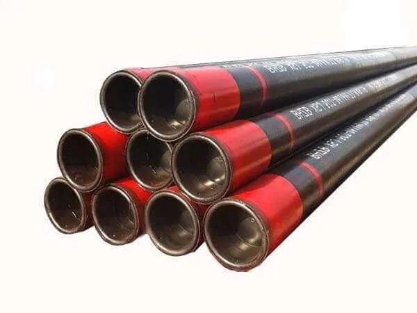
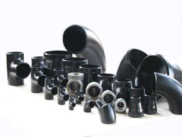
TUSPIPE offers multiple grades of API 5L pipes, each meeting the mechanical properties required by the API 5L standard. This rigorous control over pipe performance ensures that every steel pipe you encounter is perfect.
API 5L
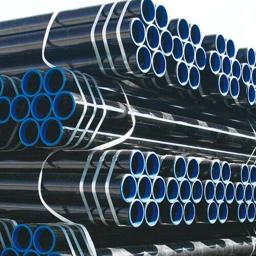
API 5L is a standard specification for line pipe that which American Petroleum Institute (API) develops and it provides the requirements for the manufacture of two product levels ( PSL1 et PSL2) of seamless and welded steel pipe for the use of the global petroleum industry, especially in the transport of crude oil, natural gas, and water.
API 5L specification 46th Edition, initially published in 1965, outlines chemical, mechanical, and hydrostatic testing criteria. Manufacturers must meet API pipe standards requirements and undergo audits to obtain a license for API 5L compliance, allowing them to showcase the API monogram on their products. License renewal every three years ensures continued adherence to quality assurance programs.
Thankfully, TUSPIPE has an API standard certificate and our api 5l consistently follows this standard!
API 5L Pipe Grands-GRADE A,B
Grade A
Steel Grade: A - Low Quality Steel
ERW size: 1/2″ NB - 16″ NB SAW/LSAW size: 16″ NB - 100″ NB Application: low pressure environment, water supply pipe Epaisseur de la paroi: Sch20-Sch xxs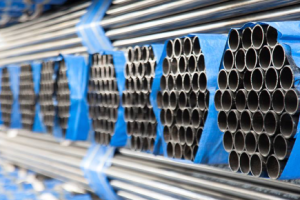
Note B
Steel Grade: B - High Quality Steel Steel Grade: X42/ X46/ X52/ X65/ X60/ X65/ X70/ X80. Application: High temperature, high pressure . environment, oil and gas transportation. Minimum Yield Strength: 205 MPa
API 5L Pipe Steels
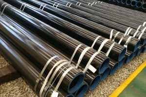
API 5L X42
Applications : manufacturing and construction, especially oil. Propriétés : pressure resistance, high strength. X42 has good welding properties and is the steel of choice for welded pipes.
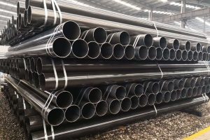
API 5L X52
Application: Can be used in PSL1/2, most commonly used steel grade. Propriétés : higher grade than X42, in high pressure applications. X52 has good weldability and formability.
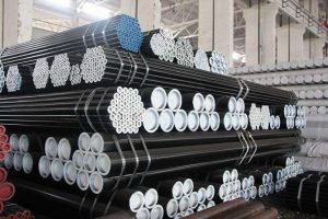
API 5L X60
Application: Can be used in PSL1/2 Propriétés : high strength/high yield X60 is suitable for acidic environments.
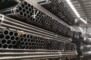
API 5L X70
Application: Long distance transportation Propriétés : super strength and durability, Yield strength 485 MPa, also called L485 pipeline steel. Known for its high tensile strength
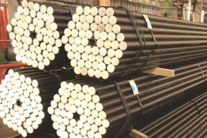
API 5L X46
Processus de fabrication : hot rolling/cold drawing/heat treatment Hot rolling: Improve ductility Cold drawing: Improvement of Yield Strength Heat treatment: Improvement of steel toughness
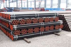
API 5L X56
Process: ERW/SMLS/LSAW/SSAW Application: Available in PSL1/2
X56 high strength, ideal for high pressure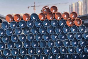
API 5L X65
Propriétés : very high con crack extension capacity
ERW: very good toughness level at low temperatures when welded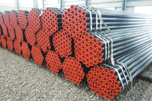
API 5L X80
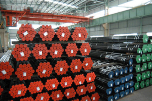
X80 line pipe is usually coated with an anti-corrosion coating, e.g. FBE/ 3LPE/ 3LPP. to protect it from harsh environments.
API 5L PSL-1
Steel Grade: A - Low Quality Steel
ERW size: 1/2″ NB - 16″ NB SAW/LSAW size: 16″ NB - 100″ NB Application: low pressure environment, water supply pipe Epaisseur de la paroi: Sch20-Sch xxs
API 5L PSL-2
Steel Grade: B - High Quality Steel Steel Grade: X42/ X46/ X52/ X65/ X60/ X65/ X70/ X80. Application: High temperature, high pressure . environment, oil and gas transportation. Minimum Yield Strength: 205 MPa
In the following, we will talk about the dimensions/mechanical properties/chemical composition/wall thickness of API 5L pipes and the pipe experimental data, etc. In order to make it easier for you to understand, we have divided the pipe data into two tables, PSL-1 and PSL-2. Hope it can help you!
Steel Grades of API 5L
API’s steel grades for line pipe standardize material chemistry and mechanical properties, ensuring adherence to set requirements. Common API 5L grade B, X42, X52, X60, and X65, with the number following ‘X’ denoting minimum yield strength in PSL. Typically used in oil and gas transport, line pipes find applications in water transport, construction, and various industries, emphasizing the importance of steel grades in selecting suitable materials.”
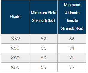
API 5L transporting categories A, B, or X fluids must be constructed from steel materials that have an area under the stress-strain curve that meets the requirements specified in the material standard. The API 5L specified minimum yield and tensile strengths “represent the point on the Stress
There are multiple grades of API 5L available, each with different yield strength and tensile strength ratings. The most common grades for API 5L line pipes are:
Dimensions and Size RANGE of API 5L(SCHEDULE CHART)
Before purchasing an API 5L , it is important to check the size and dimensions of the line pipe to ensure that it meets the required standards. The dimensions and masses of API 5L are specified in ISO 4200 and ASME B36.10M. These standards provide a guide for different size API 5L pipes and specify the wall thickness of each size. To check if a particular pipe meets the required standards, refer to these tables. Doing so will help to ensure that the pipe is the right size and has the correct wall thickness.
| NPS | O. D. | W. T. | |||||||||||||||
|---|---|---|---|---|---|---|---|---|---|---|---|---|---|---|---|---|---|
| DN | Pouce | mm | SCH5S | SCH10S | SCH10 | SCH20 | SCH30 | SCH40 | SCH60 | SCH80 | SCH100 | SCH120 | SCH140 | SCH160 | Sth | XS | XXS |
| 50 | 2″ | 60.3 | 1.65 | 2.77 | - | - | - | 3.91 | - | 5.54 | - | - | - | 8.74 | 3.91 | 5.54 | 11.07 |
| 65 | 2 1/2″ | 73 | 2.11 | 3.05 | - | - | - | 5.16 | - | 7.01 | - | - | - | 9.53 | 5.16 | 7.01 | 14.02 |
| 80 | 3″ | 88.9 | 2.11 | 3.05 | - | - | - | 5.49 | - | 7.62 | - | - | - | 11.13 | 5.49 | 7.52 | 15.24 |
| 90 | 3 1/2″ | 101.6 | 2.11 | 3.05 | - | - | - | 5.74 | - | 8.08 | - | - | - | - | 5.74 | 8.08 | - |
| 100 | 4″ | 114.3 | 2.11 | 3.05 | - | - | - | 6.02 | - | 8.58 | - | 11.13 | - | 13.49 | 6.02 | 8.56 | 17.12 |
| 125 | 5″ | 141.3 | 2.77 | 3.4 | - | - | - | 6.55 | - | 9.53 | - | 12.7 | - | 15.88 | 6.55 | 9.53 | 18.05 |
| 150 | 6″ | 168.3 | 2.77 | 3.4 | - | - | - | 7.11 | - | 10.97 | - | 14.27 | - | 18.26 | 7.11 | 10.97 | 21.95 |
| 200 | 8″ | 219.1 | 2.77 | 3.76 | - | 6.35 | 7.04 | 8.18 | 10.31 | 12.7 | 15.09 | 18.26 | 20.62 | 23.01 | 8.18 | 12.7 | 22.23 |
| 250 | 10″ | 273.1 | 3.4 | 4.19 | - | 6.35 | 7.8 | 9.27 | 12.7 | 15.09 | 18.26 | 21.44 | 25.4 | 28.58 | 9.27 | 12.7 | 25.4 |
| 300 | 12″ | 323.9 | 3.96 | 4.57 | - | 6.35 | 8.38 | 10.31 | 14.27 | 17.48 | 21.44 | 25.4 | 28.58 | 33.32 | 9.53 | 12.7 | 25.4 |
| 350 | 14″ | 355.5 | 3.96 | 4.78 | 6.35 | 7.92 | 9.53 | 11.13 | 15.09 | 19.05 | 23.83 | 27.79 | 31.75 | 35.71 | 9.53 | 12.7 | - |
| 400 | 16″ | 406.4 | 4.19 | 4.78 | 6.35 | 7.92 | 9.53 | 12.7 | 16.66 | 21.44 | 26.19 | 30.96 | 36.53 | 40.49 | 9.53 | 12.7 | - |
| 450 | 18″ | 457.2 | 4.19 | 4.78 | 6.35 | 7.92 | 11.13 | 14.27 | 19.05 | 23.83 | 39.36 | 34.93 | 39.67 | 45.24 | - | - | - |
| 500 | 20″ | 508 | 4.78 | 5.54 | 6.35 | 9.53 | 12.7 | 15.09 | 20.62 | 26.19 | 32.54 | 38.1 | 44.45 | 50.01 | - | - | - |
| 550 | 22″ | 558.8 | 4.78 | 5.54 | 6.35 | 9.53 | 12.7 | - | 22.23 | 28.58 | 34.93 | 41.28 | 47.63 | 53.98 | - | - | - |
| 600 | 24″ | 609.6 | 5.54 | 6.35 | 6.35 | 9.53 | 14.27 | 17.48 | 24.61 | 30.96 | 38.89 | 46.02 | 52.37 | 59.54 | - | - | - |
Chemical composition of API 5L
The chemical composition of API 5L pipe contains the content of each element as well as carbon equiva, in addition, TUSPIPE also categorizes the chemical composition into API 5L seamless pipe and welded pipe two kinds of process demonstration, I hope it can help you!
| Qualité de l'acier | Mass fraction, % based on heat and product analyses a,g | ||||||
|---|---|---|---|---|---|---|---|
| C | Mn | P | S | V | Nb | Ti | |
| max | max | max | max | max | max | max | |
| Tube sans soudure | |||||||
| A | 0.22 | 0.9 | 0.03 | 0.03 | - | - | - |
| B | 0.28 | 1.2 | 0.03 | 0.03 | c,d | c,d | d |
| X42 | 0.28 | 1.3 | 0.03 | 0.03 | d | d | d |
| X46 | 0.28 | 1.4 | 0.03 | 0.03 | d | d | d |
| X52 | 0.28 | 1.4 | 0.03 | 0.03 | d | d | d |
| X56 | 0.28 | 1.4 | 0.03 | 0.03 | d | d | d |
| X60 | 0.28 e | 1.40 e | 0.03 | 0.03 | f | f | f |
| X65 | 0.28 e | 1.40 e | 0.03 | 0.3 | f | f | f |
| X70 | 0.28 e | 1.40 e | 0.03 | 0.03 | f | f | f |
| Tube soudé | |||||||
| A | 0.22 | 0.9 | 0.03 | 0.03 | - | - | - |
| B | 0.26 | 1.2 | 0.03 | 0.03 | c,d | c,d | d |
| X42 | 0.26 | 1.3 | 0.03 | 0.03 | d | d | d |
| X46 | 0.26 | 1.4 | 0.03 | 0.03 | d | d | d |
| X52 | 0.26 | 1.4 | 0.03 | 0.3 | d | d | d |
| X56 | 0.26 | 1.4 | 0.3 | 0.03 | d | d | d |
| X60 | 0.26 e | 1.40 e | 0.03 | 0.03 | f | f | f |
| X65 | 0.26 e | 1.45 e | 0.03 | 0.03 | f | f | f |
| X70 | 0.26e | 1.65 e | 0.03 | 0.03 | f | f | f |
| a. Cu ≤ = 0.50% Ni; ≤ 0.50%; Cr ≤ 0.50%; and Mo ≤ 0.15%, b. For each reduction of 0.01% below the specified maximum concentration for carbon, an increase of 0.05% above the specified maximum concentration for Mn is permissible, up to a maximum of 1.65% for grades ≥ L245 or B, but ≤ L360 or X52; up to a maximum of 1.75% for grades > L360 or X52, but < L485 or X70; and up to a maximum of 2.00% for grade L485 or X70., c. Unless otherwise agreed NB + V ≤ 0.06%, d. Nb + V + TI ≤ 0.15%, e. Unless otherwise agreed., f. Unless otherwise agreed, NB + V = Ti ≤ 0.15%, g. No deliberate addition of B is permitted and the residual B ≤ 0.001% | |||||||
| Qualité de l'acier | Mass fraction, % based on heat and product analyses | Carbon Equiv a | ||||||||||||||||||
|---|---|---|---|---|---|---|---|---|---|---|---|---|---|---|---|---|---|---|---|---|
| C | Si | Mn | P | S | V | Nb | Ti | Autres | CE IIW | CE Pcm | ||||||||||
| max | max | max | max | max | max | max | max | max | max | |||||||||||
| Seamless Pipe | ||||||||||||||||||||
| BR | 0.24 | 0.4 | 1.2 | 0.025 | 0.015 | c | c | 0.04 | e,l | 0.043 | 0.25 | |||||||||
| X42R | 0.24 | 0.4 | 1.2 | 0.025 | 0.015 | 0.06 | 0.05 | 0.04 | e,l | 0.043 | 0.25 | |||||||||
| BN | 0.24 | 0.4 | 1.2 | 0.025 | 0.015 | c | c | 0.04 | e,l | 0.043 | 0.25 | |||||||||
| X42N | 0.24 | 0.4 | 1.2 | 0.025 | 0.015 | 0.06 | 0.05 | 0.04 | e,l | 0.043 | 0.25 | |||||||||
| X46N | 0.24 | 0.4 | 1.4 | 0.025 | 0.015 | 0.07 | 0.05 | 0.04 | d,e,l | 0.043 | 0.25 | |||||||||
| X52N | 0.24 | 0.45 | 1.4 | 0.025 | 0.015 | 0.1 | 0.05 | 0.04 | d,e,l | 0.043 | 0.25 | |||||||||
| X56N | 0.24 | 0.45 | 1.4 | 0.025 | 0.015 | 0.10f | 0.05 | 0.04 | d,e,l | 0.043 | 0.25 | |||||||||
| X60N | 0.24f | 0.45f | 1.40f | 0.025 | 0.015 | 0.10f | 0.05f | 0.04f | g,h,l | Comme convenu | ||||||||||
| BQ | 0.18 | 0.45 | 1.4 | 0.025 | 0.015 | 0.05 | 0.05 | 0.04 | e,l | 0.043 | 0.25 | |||||||||
| X42Q | 0.18 | 0.45 | 1.4 | 0.025 | 0.015 | 0.05 | 0.05 | 0.04 | e,l | 0.043 | 0.25 | |||||||||
| X46Q | 0.18 | 0.45 | 1.4 | 0.025 | 0.015 | 0.05 | 0.05 | 0.04 | e,l | 0.043 | 0.25 | |||||||||
| X52Q | 0.18 | 0.45 | 1.5 | 0.025 | 0.015 | 0.05 | 0.05 | 0.04 | e,l | 0.043 | 0.25 | |||||||||
| X56Q | 0.18 | 0.45f | 1.5 | 0.025 | 0.015 | 0.07 | 0.05 | 0.04 | e,l | 0.043 | 0.25 | |||||||||
| X60Q | 0.18f | 0.45f | 1.70f | 0.025 | 0.015 | g | g | g | h,l | 0.043 | 0.25 | |||||||||
| X65Q | 0.18f | 0.45f | 1.70f | 0.025 | 0.015 | g | g | g | h,l | 0.043 | 0.25 | |||||||||
| X70Q | 0.18f | 0.45f | 1.80f | 0.025 | 0.015 | g | g | g | h,l | 0.043 | 0.25 | |||||||||
| X80Q | 0.18f | 0.45f | 1.90f | 0.025 | 0.015 | g | g | g | i,j | Comme convenu | ||||||||||
| X90Q | 0.16f | 0.45f | 1.9 | 0.02 | 0.01 | g | g | g | j,k | Comme convenu | ||||||||||
| X100Q | 0.16f | 0.45f | 1.9 | 0.02 | 0.01 | g | g | g | j,k | Comme convenu | ||||||||||
| Tube soudé | ||||||||||||||||||||
| BM | 0.22 | 0.45 | 1.2 | 0.025 | 0.015 | 0.05 | 0.05 | 0.04 | e,l | 0.043 | 0.25 | |||||||||
| X42M | 0.22 | 0.45 | 1.3 | 0.025 | 0.015 | 0.05 | 0.05 | 0.04 | e,l | 0.043 | 0.25 | |||||||||
| X46M | 0.22 | 0.45 | 1.3 | 0.025 | 0.015 | 0.05 | 0.05 | 0.04 | e,l | 0.043 | 0.25 | |||||||||
| X52M | 0.22 | 0.45 | 1.4 | 0.025 | 0.015 | d | d | d | e,l | 0.043 | 0.25 | |||||||||
| X56M | 0.22 | 0.45f | 1.4 | 0.025 | 0.015 | d | d | d | e,l | 0.043 | 0.25 | |||||||||
| X60M | 0.12f | 0.45f | 1.60f | 0.025 | 0.015 | g | g | g | h,l | 0.043 | 0.25 | |||||||||
| X65M | 0.12f | 0.45f | 1.60f | 0.025 | 0.015 | g | g | g | h,l | 0.043 | 0.25 | |||||||||
| X70M | 0.12f | 0.45f | 1.70f | 0.025 | 0.015 | g | g | g | h,l | 0.043 | 0.25 | |||||||||
| X80M | 0.12f | 0.45f | 1.85f | 0.025 | 0.015 | g | g | g | i,j | .043f | 0.25 | |||||||||
| X90M | 0.1 | 0.55f | 2.10f | 0.02 | 0.01 | g | g | g | i,j | - | 0.25 | |||||||||
| X100M | 0.1 | 0.55f | 2.10f | 0.02 | 0.01 | g | g | g | i,j | - | 0.25 | |||||||||
| a. SMLS t>0.787”, CE limits shall be as agreed. The CEIIW limits applied fi C > 0.12% and the CEPcm limits apply if C ≤ 0.12%, b. For each reduction of 0.01% below the specified maximum for C, an increase of 0.05% above the specified maximum for Mn is permissible, up to a maximum of 1.65% for grades ≥ L245 or B, but ≤ L360 or X52; up to a maximum of 1.75% for grades > L360 or X52, but < L485 or X70; up to a maximum of 2.00% for grades ≥ L485 or X70, but ≤ L555 or X80; and up to a maximum of 2.20% for grades > L555 or X80., c. Unless otherwise agreed Nb = V ≤ 0.06%, d. Nb = V = Ti ≤ 0.15%, e. Unless otherwise agreed, Cu ≤ 0.50%; Ni ≤ 0.30% Cr ≤ 0.30% and Mo ≤ 0.15%, f. Unless otherwise agreed, g. Unless otherwise agreed, Nb + V + Ti ≤ 0.15%, h. Unless otherwise agreed, Cu ≤ 0.50% Ni ≤ 0.50% Cr ≤ 0.50% and MO ≤ 0.50%, i. Unless otherwise agreed, Cu ≤ 0.50% Ni ≤ 1.00% Cr ≤ 0.50% and MO ≤ 0.50%, j. B ≤ 0.004%, k. Unless otherwise agreed, Cu ≤ 0.50% Ni ≤ 1.00% Cr ≤ 0.55% and MO ≤ 0.80%, l. For all PSL 2 pipe grades except those grades with footnotes j noted, the following applies. Unless otherwise agreed no intentional addition of B is permitted and residual B ≤ 0.001%. |
||||||||||||||||||||
Mechanical Properties of API 5L standards
| Qualité du tube | Pipe body of seamless and welded pipes | Weld seam of EW, SAW and COW pip | ||
|---|---|---|---|---|
| Yield strength R10,5MPa(psi) minimum | Résistance à la traction RmMPa(psi) minimum | Élongation Af% minimum | Tensile strength RmMPa(psi) minimum | |
| L175 or A25 | 175 (25 400) | 310 (45 000) | c | 310 (45 000) |
| L175P or A25P | 175 (25 400) | 310 (45 000) | c | 310 (45 000) |
| L210 or A | 210 (30 500) | 335 (48 600) | c | 335 (48 600) |
| L245R or BR L245 or B | 245 (35 500) | 415 (60 200) | c | 415 (60 200) |
| L290R or X42R L290 or X42 | 290 (42 100) | 415 (60 200) | c | 415 (60 200) |
| L320 or X46 | 320 (46 400) | 435 (63 100) | c | 435 (63 100) |
| L360 or X52 | 360 (52 200) | 460 (66 700) | c | 460 (66 700) |
| L390 or X56 | 390 (56 600) | 490 (71 100) | c | 490 (71 100) |
| L415 or X60 | 415 (60 200) | 520 (75 400) | c | 520 (75 400) |
| L450 or X65 | 450 (65 300) | 535 (77 600) | c | 535 (77 600) |
| L485 or X70 | 485 (70 300) | 570 (82 700) | c | 570 (82 700) |
| Pipe grade | Pipe body of seamless and welded pipes | Weld seam of HFW, SAW and COW pipes | |||||
|---|---|---|---|---|---|---|---|
| Yield strength Rto,5b MPa (psi) | Résistance à la traction Rm MPa (psi) | Ratioa,b,c Rto,5/Rm | Élongation Af % | Résistance à la traction Rm MPa (psi) | |||
| minimum | maximum | minimum | maximum | maximum | minimum | minimum | |
| L245R ou BR L245N ou BN L245Q ou BQ L245M ou BM | 245 (35 500) | 450 e (65 300) e | 415 (60 200) | 760 (110 200) | 0,93 | f | 415 (60 200) |
| L290R ou X42R L290N ou X42N L290Q ou X42Q L290M ou X42M | 290 (42 100) | 495 (71 800) | 415 (60 200) | 760 (110 200) | 0,93 | f | 415 (60 200) |
| L320N ou X46N L320Q ou X46Q L320M ou X46M | 320 (46 400) | 525 (76 100) | 435 (63 100) | 760 (110 200) | 0,93 | f | 435 (63 100) |
| L360N ou X52N L360Q ou X52Q L360M ou X52M | 360 (52 200) | 530 (76 900) | 460 (66 700) | 760 (110 200) | 0,93 | f | 460 (66 700) |
| L390N ou X56N L390Q ou X56Q L390M ou X56M | 390 (56 600) | 545 (79 000) | 490 (71 100) | 760 (110 200) | 0,93 | f | 490 (71 100) |
| L415N ou X60N L415Q ou X60Q L415M ou X60M | 415 (60 200) | 565 (81 900) | 520 (75 400) | 760 (110 200) | 0,93 | f | 520 (75 400) |
| L450Q ou X65Q L450M ou X65M | 450 (65 300) | 600 (87 000) | 535 (77 600) | 760 (110 200) | 0,93 | f | 535 (77 600) |
| L485Q ou X70Q L485M ou X70M | 485 (70 300) | 635 (92 100) | 570 (82 700) | 760 (110 200) | 0,93 | f | 570 (82 700) |
| L555Q ou X80Q L555M ou X80M | 555 (80 500) | 705 (102 300) | 625 (90 600) | 825 (119 700) | 0,93 | f | 625 (90 600) |
| L625M ou X90M | 625 (90 600) | 775 (112 400) | 695 (100 800) | 915 (132 700) | 0,95 | f | 695 (100 800) |
| L690M ou X100M | 690 (100 100) | 840 (121 800) | 760 (110 200) | 990 (143 600) | 0,97 g | f | 760 (110 200) |
| L830M ou X120M | 830 (120 400) | 1 050 (152 300) | 915 (132 700) | 1 145 (166 100) | 0,99 g | f | 915 (132 700) |
api 5l specification:Production Tolerances
This section demonstrates the tolerances of the API 5L piping specification, to which TUSPIPE adheres to produce piping! Here you can see the API 5L specification OD tolerances / API 5L wall thickness tolerances and length tolerances.
In addition, you can also see the frequency and standard of testing of API 5L pipes, TUSPIPE has its own inspection and testing laboratory and supports third-party inspections, as we believe that quality makes all the difference.
We hope that this information will help you to make a better choice of piping
- API 5L Outside Diameter and Out of Roundness Tolerance
| Specified Outside Diameter D (in) | Diameter Tolerance, inches d | Out-of-Roundness Tolerance in | ||||
|---|---|---|---|---|---|---|
| Pipe except the end a | Pipe end a,b,c | Pipe except the End a | Pipe End a,b,c | |||
| Tube SMLS | Tube soudé | Tube SMLS | Tube soudé | |||
| < 2.375 | -0.031 to + 0.016 | – 0.031 to + 0.016 | 0.048 | 0.036 | ||
| ≥2.375 to 6.625 | +/- 0.0075D | – 0.016 to + 0.063 | 0.020D for | 0.015D for | ||
| n/t≤75 | n/t≤75 | |||||
| By agreement for | By agreement for | |||||
| n/t≤75 | n/t≤75 | |||||
| >6.625 to 24.000 | +/- 0.0075D | +/- 0.0075D, but max of 0.125 | +/- 0.005D, but max of 0.063 | 0.020D | 0.015D | |
| >24 to 56 | +/- 0.01D | +/- 0.005D but max of 0.160 | +/- 0.079 | +/- 0.063 | 0.015D for but max of 0.060 | 0.01D for but max of 0.500 |
| For | For | |||||
| n/t≤75 | n/t≤75 | |||||
| By agreement | By agreement | |||||
| for | for | |||||
| n/t≤75 | n/t≤75 | |||||
| >56 | Comme convenu | |||||
| a. The API 5L pipe end includes a length of 4 in ate each of the pipe extremities | ||||||
| b. For SMLS pipe the tolerance apply for t≤0.984in and the tolerances for the thicker pipe shall be as agreed | ||||||
| c. For expanded pipe with D≥8.625in and for non-expanded pipe, the diameter tolerance and the out-of-roundness tolerance may be determined using the calculated inside diameter or measured inside diameter rather than the specified OD. | ||||||
| d. For determining compliance to diameter tolerance, the pipe diameter is defined as the circumference of the pipe in any circumferential plane divide by Pi. | ||||||
- API 5L Wall Thickness Tolerances
| Epaisseur de la paroi t mm (in) | Tolerances a mm (in) |
|---|---|
| Seamless pipe b | |
| ≤ 4,0 ( 0.157) | + 0,6 (0.024) – 0,5 (0.020) |
| > 4,0 ( 0.157) to <25,0 (0.984) | + 0,150 – 0,125 |
| ≥ 25,0 (0.984) | +3,7 (0.146) or + 0,1 t, whichever is the greater – 3,0 (0.120) or – 0,1 t, whichever is the greater |
| Welded pipe c, d | |
| ≤ 5,0 (0.197) | ± 0,5 (0.020) |
| > 5,0 (0.197) to <15,0 (0.591) | ± 0,1 t |
| ≥ 15,0 (0.591) | ±1,5 (0.060) |
a If the purchase order specifief a minus tolerance for wall thickness smaller than the applicable value given in this table, the plus tolerance for wall thickness shall be increased by an amount sufficient to maintain the applicable tolerance range.
b For API 5L pipe with D ≥ 355,6 mm (14.000 in) and t ≥ 25,0 mm (0.984 in) the wall-thickness tolerance locally may exceed the plus tolerance for wall thickness by an additional 0,05 t, provided that the plus tolerance for mass (see 9.14) is not exceeded.
c The plus tolerance for wall thickness does not apply to the weld area.
d See 9.13.2 for additional restrictions.
- API 5L Length Tolerances
According to the requirements outlined in API 5L, random lengths of line pipe shall be delivered within the tolerances given below, and approximate lengths must be delivered within ± 500 mm (20 in.). Additionally, if the supply of jointers is agreed upon, jointers comprising two pieces welded together to make a length shorter than 15.0 m (49.2 ft) may be furnished to a maximum of 5 % of the order item, or as agreed. Jointers comprising three pieces welded together to make a length 15.0 m (49.2 ft) or longer may also be furnished for the entire order item or any portion thereof, though this is limited to a maximum of 5 % of the order item as well. These requirements ensure that API 5L are of the correct length and can be properly joined together when necessary.
| Random length designation | Minimum length | Minimum average length for each order item | Maximum length |
|---|---|---|---|
| m (ft) | m (ft) | m(ft) | m(ft) |
| Threaded-and-coupled pipe | |||
| 6 (20) | 4.88 (16.0) | 5.33 (17.5) | 6.86 (22.5) |
| 9 (30) | 4.11 (13.5) | 8.00 (26.2) | 10.29 (33.8) |
| 12 (40) | 6.71 (22.0) | 10.67 (35.0) | 13.72 (45.0) |
| Plain-end pipe | |||
| 6 (20) | 2.74 (9.0) | 5.33 (17.5) | 6.86 (22.5) |
| 9 (30) | 4.11 (13.5) | 8.00 (26.2) | 10.29 (33.8) |
| 12 (40) | 4.27 (14.0) | 10.67 (35.0) | 13.72 (45.0) |
| 15 (50) | 5.33 (17.5) | 13.35 (43.8) | 16.76 (55.0) |
| 18 (60) | 6.40 (21.0) | 16.00 (52.5) | 19.81 (65.0) |
| 24 (80) | 8.53 (28.0) | 21.34 (70.0) | 25.91 (85.0) |
Inspection Frequency for API 5L
- Inspection Frequency for API 5L PSL 1
| No | Type of Inspection | Type | Frequency of Inspection e |
|---|---|---|---|
| 1 | Heat analysis | All pipe | One analysis per heat of steel |
| 2 | Analyse des produits | SMLS,CW,LFW,HFW,LW.SAW,or COW | Two analyses per heat of steel (taken from separate product items) |
| 3 | Tensile testing of the pipe body of welded pipe with D ≤ 48.3 mm(1.900 in.),in Grade L175 or A25 | CW, LFW,or HFW | Once per test unit e of not more than 25 tonnes(28 tons) of pipe |
| 4 | Tensile testing of the pipe body of welded pipe with D ≤ 48.3 mm(1.900 in.),in Grade L175P or A25P | CW | Once per test unit e of not more than 25 tonnes(28 tons) of pipe |
| 5 | Tensile testing of the pipe body of welded pipe with D > 48.3 mm(1.900 in.),in Grade L175 or A25 | CW,LFW,or HFW | Once per test unit of not more than 50 tonnes(55 tons) of pipe |
| 6 | Tensile testing of the pipe body of welded pipe with D > 48.3 mm(1.900 in.),in Grade L175P or A25P | CW | Once per test unit of not more than 50 tonnes(55 tons)of pipe |
| 7 | Tensile testing of the pipe body of seamless pipe | SMLS | Once per test unit of pipe with the same cold-expansion ratio a |
| 8 | Tensile testing of the pipe body of welded pipe in grades higher than Grade L175 or A25 | LFW,HFW,LW,SAW,or CoW | Once per test unit of pipe with the same cold-expansion ratio a |
| 9 | Tensile testing of the longitudinal or helical seam weld of welded pipe with D ≥ 219.1 mm (8.625 in.). | LFW,HFWLW,SAW,or Cow | Once per test unit of pipe with the same cold-expansion ratio a,b,c |
| 10 | Tensile testing of the coil/plate end weld of welded pipe with D ≥ 219.1 mm (8.625 in.). | SAWH or COWH | At least once per 50 coil/plate end welds from pipe with the same cold-expansion ratio a,c,d |
| 11 | Bend testing of the longitudinal seam weld of welded pipe with D ≤ 48.3 mm(1.900 in.),in Grade L175, L175P, A25,or A25P | CW,LFW,or HFW | Once per test unit of not more than 25 tonnes(28 tons) of pipe |
| 12 | Bend testing of the longitudinal seam weld of welded pipe with 48.3 mm(1.900 in.)<D ≤ 60.3 mm (2.375 in.).in Grade L175,L175P,A25,or A25P | CW,LFW,or HFW | Once per test unit of not more than 50 tonnes(55 tons) of pipe |
| 13 | Guided-bend testing of the longitudinal or helical seam weld of welded pipe | SAW or COW | Once per test unit of not more than 50 lengths of pipe of the same grade |
| 14 | Guided-bend testing of the coil/plate end weld of welded pipe | SAWH or COWH | At least once per 50 col/plate end welds from pipe with the same cold expansion ratio a,c,d |
| 15 | Guided-bend testing of the longitudinal seam weld of welded pipe with D ≥ 323.9 mm (12.750 in.) | LW | Once per test unit of not more than 50 lengths of pipe of the same grade |
| 16 | Flattening test of welded pipe | CW,LFW,HFW,or LW | As shown in Figure 6 |
| 17 | Hardness testing of hard spots in cold-formed welded pipe | LFW,HFW,LW,SAW,or COW | Any hard spot exceeding 50 mm (2.0 in.) in any direction |
| 18 | Essais hydrostatiques | SMLS,CW,LFW,HFW,LWSAW,or COW | Each pipe |
| 19 | Macrographic testing of the longitudinal or helical seam weld of welded pipe | SAW or COW | At least once per operating shift plus whenever any change of pipe size occurs during the operating shift; or if 10.2.5.2 applies, at the beginning of the production of each combination of specified outside diameter and specified wall thickness |
| 20 | Metallographic testing of the longitudinal seam weld of welded pipe | LFW or HFW excluding full-body normalized pipe | At least once per operating shift plus whenever changes of grade, specified outside diameter or specified wall thickness are made:plus whenever excursions from operating heat treatment conditions are encountered |
| 21 | Visual inspection | SMLS,CW,LFW,HFW,LW,SAW,or COW | Each pipe, except as allowed by 10.2.7.2 |
| 22 | Pipe diameter and out-of-roundness | SMLS,CW,LFW,HFW,LW,SAW,or COW | At least once per 4 h per operating shift plus whenever any change of pipe size occurs during the operating shift |
| 23 | Wall thickness measurement | All pipe | Each pipe (see 10.2.8.5) |
| 24 | Other dimenslonal testing | SMLS,CW,LFW,HFW,LW,SAW,or COW | Random testing,with the details left tothe discretion of the manufacturer |
| 25 | Weighing of pipe with D <141.3 mm (5.563 in.) | SMLS,CW,LFW,HFW,LW,SAW,or COW | Each pipe or each convenient group of pipe, with the choice being at the discretion of the manufacturer |
| 26 | Weighing of pipe with D ≥141.3 mm (5.563 in.) | SMLS,CW,LFW,HFW,LW,SAW,or COW | Each pipe |
| 27 | Longueur | SMLS,CW,LFW,HFW,LW,SAW,or COW | Each length of pipe shall be measured, except that pipe made in lengths that are uniform within 30 mm (0.1 ft) need not be individually measured, provided the accuracy of the length is verified at least once per 4 h per operating shift |
| 28 | Nondestructive inspection | SMLS,CW,LFW,HFW,LW,SAW,or COW | In accordance with Annex E |
a The cold-expansion ratio (if applicable) is designated by the manufacturer and is derived using the designated before-expansion outside diameter or circumference and the after-expansion outside diameter or circumference; an increase or decrease in the cold-expansion ratio of more than 0.002 requires the creation of a new test unit.
b For double-seam pipe, both longitudinal weld seams in the pipe selected to represent the test unit shall be tested.
c Pipe produced by each welding machine shall be tested at least once per week.
d Applies only to finished helical seam pipe containing coil/plate end welds.
e “Test unit””is as defined in 3.1.60.
- Inspection Frequency for API 5L PSL 2
| No | Type of Inspection | Type de tuyau | Frequency of Inspection e |
|---|---|---|---|
| 1 | Hea analysis | All pipe | One analysis per heat of steel |
| 2 | Analyse des produits | SMLS , HFW , SAW , orCOW | Two analyses per heat of steel ( taken from separate product items ) |
| 3 | Tensile testing of the pipe body D ≤141.3 mm (5.563 in .) | SMLS , HFW , SAW , or COW | Once per test unit of not more than 400 pipes with the same cold – expansion ratio a |
| 4 | Tensile testing of the pipe body D >141.3mm(5.563in.) and ≤323.9 body mm (12.750 in .) | SMLS , HFW , SAW , or COW | Once per test unit of not more than 200 pipes with the same cold – expansion ratio a |
| 5 | Tensile testing of the pipe D >323.9 mm (12.750 in .) | SMLS,HFW , SAW , or COW | Once per test unit of not more than 100 pipes with the same cold – expansion ratio a |
| 6 | Tensile testing of the longitudinal or helical seam weld of welded pipe with D ≥219.1 mm (8.625 in .) and ≤323.9 mm (12.750 in .) | HFW , SAW , or COW | Once per test unit of not more than 200 pipes with the same cold – expansion ratio a . b , c |
| 7 | Tensile testing of the longitudinal or helical seam weld of welded pipe with D >323.9 mm (12.750 in .) | HFW , SAW , or COW | Once per test unit of not more than 100 pipes with the same cold – expansion ratio a , b . c |
| 8 | Tensile testing of the coil / plate end weld of welded pipe with D ≥219.1 mm (8.625 in .) | SAWH or COWH | At least once per 50 coil / plate end welds from pipe with the same cold – expansion ratio a , b , d |
| 9 | CVN impact testing of the pipe body of pipe with specified outside diameter and specified wall thickness as given in Table 22 | SMLS , HFW , SAW , or COW | Once per test unit of pipe with the same cold – expansion ratio a |
| 10 | If agreed , CVN impact testing of the longitudinal seam weld of welded pipe specified wall thickness as given in with specified outside diameter and Table 22 | HFW | Once per test unit of pipe with the same cold – expansion ratio a , b |
| 11 | CVN impact testing of the longitudinal or helical seam weld of welded pipe specified wall thickness as given in with specified outside diameter and Table 22 | SAW or COW | Once per test unit of pipe with the same cold – expansion ratio a . b . c |
| 12 | CVN impact testing of the coil / plate end weld of welded pipe with specified outside diameter and specified wall thickness as given in Table 22 | SAWH or COWH | At least once per 50 coil / plate end welds from pipe with the same cold – expansion ratio a , b , d |
| 13 | If agreed , DWT testing of the pipe body of welded pipe with D ≥508 mm (20.000 in .) | HFW , SAW , or COW | Once per test unit of pipe with the same cold – expansion ratio a |
| 14 | Guided – bend testing of the longitudinal or helical seam weld of welded pipe | SAW or COW | Once per test unit of not more than 50 lengths of pipe with the same cold – expansion ratio |
| 15 | Guided – bend testing of the coil / plate end weld of welded pipe | SAWH or COWH | At least once per 50 coil / plate end welds from pipe with the same cold – expansion ratio a , b . d |
| 16 | Flattening test of welded pipe | HFW | As shown in Figure 6 |
| 17 | Hardness testing of hard spots in cold -formed welded pipe | HFW , SAW , or COw | Any hard spot exceeding 50 mm (2.0 in .) in any direction |
| 18 | Essais hydrostatiques | SMLS , HFW , SAW , or COW | Each pipe |
| 19 | Macrographic testing of the longitudinal or helical seam weld of welded pipe | SAW or COW | At least once per operating shift plus whenever any change of pipe size occurs during the operating shift ; or , if 10.2.5.3 or 10.2.5.4 applies , at the beginning of the production of each combination of specified outside diameter and specified wall thickness |
| 20 | Metallographic testing ( or optional hardness test in lieu of metallography )of the longitudinal seam weld of welded pipe | HFW excluding full – body normal | At least once per operating shift plus whenever changes of grade , specified outside diameter or specified wall thickness are made ; plus whenever excursions from operating heat treatment conditions are encountered |
| 21 | Visual inspection | SMLS,HFW,SAW,OR COW | Each pipe , except as allowed by 10.2.7.2 |
| 22 | Pipe diameter and out – of – roundness | SMLS,HFW,SAW,OR COW | At least once per 4 h per operating shift plus whenever any change of pipe size occurs during the operating shift |
| 23 | Wall thickness measurement | All pipe | Each pipe ( see 10.2.8.5) |
| 24 | Other dimensional testing | SMLS,HFW,SAW,OR COW | Random testing , with the details left to the discretion of the manufacturer |
| 25 | Weighing of pipe withD <141.3 mm (5.563 in .) | SMLS,HFW,SAW,OR COW | Each pipe or each convenient group of pipe , with the choice being at the discretion of the manufacturer |
| 26 | Weighing of pipe with D 2141.3 mm (5.563 in .) | SMLS,HFW,SAW,OR COW | Each pipe |
| 27 | Longueur | SMLS,HFW,SAW,OR COW | Each length of pipe shall be measured , except that pipe made in lengths that are uniform within 30 mm (0.1 ft ) need not b individually measured , provided the accuracy of the length is verified at least once per 4 h per operating shift |
| 28 | Nondestructive inspection | SMLS,HFW,SAW,OR COW | In accordance with Annex E |
| a. The cold – expansion ratio ( if applicable ) is designated by the manufacturer and is derived using the designated before – expansion outside diameter or circumference and the after – expansion outside diameter or circumference ; an increase or decrease in the cold – expansion ratio of more than 0.002 requires the creation of a new test unit . b. Pipe produced by each welding machine shall be tested at least once per week . c. For double – seampipe , both longitudinal weld seams in the pipe selected to represent the test unit shall be tested . d. Applies only to finished helical seam pipe containing coil / plate end welds . e. ” Test unit ” is as defined in 3.1.60. | |||
Test and inspection of API 5L
- Test hydrostatique
A hydrostatic test is a type of pressure test that is commonly used during the production of line pipes. The test is used to check for leaks in the weld seam or pipe body. To conduct the test, water is pumped into the pipe until it reaches a predetermined pressure. The pipe is then monitored for any leaks. If a leak is detected, the pipe will need to be repaired or replaced. The hydrostatic test is an important quality control measure that helps to ensure the safety and integrity of pipes.
- Bending Test
A bending test is a type of quality control test that is performed during steel pipe production. The purpose of the test is to check for cracks in the welds, as well as to assess the strength of the steel. To perform the test, a sample piece of pipe is bent into a U-shape. The steel is then examined for cracks or other signs of weakness. If any are found, the entire batch of steel pipes will be scrapped and a new batch will be made. However, if the bending test proves successful, the steel pipes will be approved for use.
- Test d'aplatissement
A flattening test is a steel line pipe production test that assesses a steel tube’s resistance to deformation and cracking under stress. It is an important quality control measure that helps ensure the steel used in line pipe products is of the highest possible quality. The test involves applying pressure to a steel tube until it deforms or cracks. The flattening test will reveal the pipe’s resistance to longitudinal and circumferential cracking. The results of the test help determine the steel’s strength and ductility, two important properties for steel used in line pipe applications. Flattening tests are just one of many quality control measures that are used during steel line pipe production, but they play an important role in ensuring the safety and integrity of the final product.
- Test d'impact CVN
The CVN impact test is a temperature test that is conducted during pipe production in order to ensure the mechanical properties of the pipe. The test is conducted on three different positions on the pipe: the body, the welding seam, and the heat-affected zone. The results of the test are used to determine the Charpy V-notch impact strength of the pipe. The CVN impact test is an important quality control measure for pipe production, and it is required by the American Petroleum Institute (API) in order to meet its standards.
- DWTT
The DWTT test, or drop-weight tear tests, are specified in the API 5L production specification. In this test, a large weight is dropped onto a pre-weakened point on a sample of pipe. The resulting fracture is examined to ensure that it meets the requirements for ductile fracture behavior. This test is important because it helps to ensure that pipes will be able to withstand the stress of being transported and installed without breaking. As a result, the DWTT test is an essential part of the quality control process for large diameter line pipes.
Why choose tuspipe API 5L

TUSPIPE stands tall as an indispensable ally for the oil and gas industry. Our pipes serve as the very lifelines that efficiently channel vital resources. Understanding the criticality of high-performing pipes in this sector, we engineer our products to withstand the rigorous demands and aggressive environments typical of oil and gas applications. Our pipes are compliant with stringent API 5L specifications, ensuring unmatched strength and durability. Our heat treatment and inspection capabilities further fortify welds and eradicate leaks. Moreover, TUSPIPE’s anti-corrosion services, such as FBE, 3LPE, and 3LPP coatings, guarantee long-lasting resilience against corrosion – a non-negotiable necessity for oil and gas pipelines.
How to Select an API 5L Certified Line Pipe Supplier in China?
When selecting an API 5L certified supplier in China, it is important to be aware of the fake certificates that some companies use. These fake certificates are often created using photoshop and can be very difficult to identify. However, they can often trick buyers into thinking they are getting a high-quality product when in reality the product is of low quality and may even be dangerous. This damages the projects that use these pipes because they are not up to code and they can cause safety issues. If something goes wrong, the company that chose the line pipe supplier with a fake certificate can be sued and lose a lot of money in compensation payments. Don’t let this happen to your company! As such, it is always best to select a reputable and trustworthy supplier who can provide you quality pipes with a genuine API 5L certificate. This will help to ensure the safety of your business and avoid any potential legal problems. Next, I’ll show you how to spot fake certificates.
1. Check the API Composite List
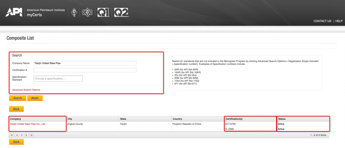
The Composite List is a directory of all the companies that are certified by the American Petroleum Institute (API). This list can be used to check if a line pipe manufacturer is authorized to use the API logo on its products. To search the Composite List,
1) Go to the API official website and find the “API Composite List” tab;
2) You will see the screenshot above, type in the company name or certification number, and click “Search”;
3) Finally, you will see the company detail about the certification types and the certification status.
If the certification type is what you are looking for, and the certificate status also shows “Active”, then you are safe at this stage. While you may also interested in checking the company details to see if you are dealing with the right person, you can click on the company name shown in red.
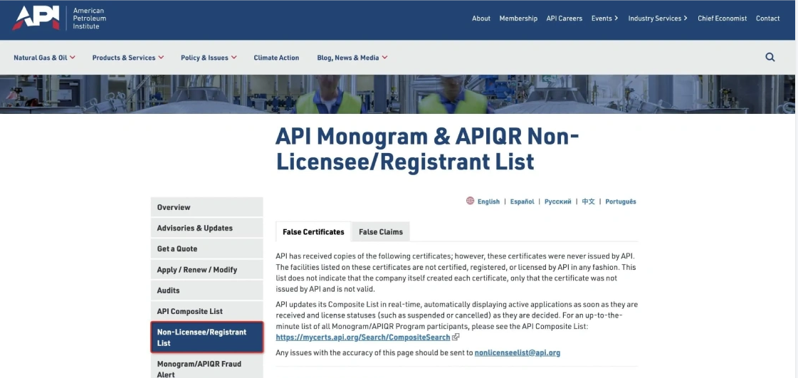
2. Check the Non-Licensee / Registrant List
The American Petroleum Institute (API) also released a list showing all the cheater companies that API has found in the past, and these companies are still in the market. The API Non-Licensee/Registrant List is a great resource for finding unqualified suppliers who are holding fake certificates. Here is how to check the list:
1) Go to the API official website and find the “Non-Licensee/Registrant List” tab;
2) Scroll down to find all the cheater companies who may want to fool you with a fake license.
You can use this information to help you narrow down your search for a qualified line pipe supplier. If you are looking for a specific company, you can type the company name in the “Search” box.
3. Check the MTC from the Supplier
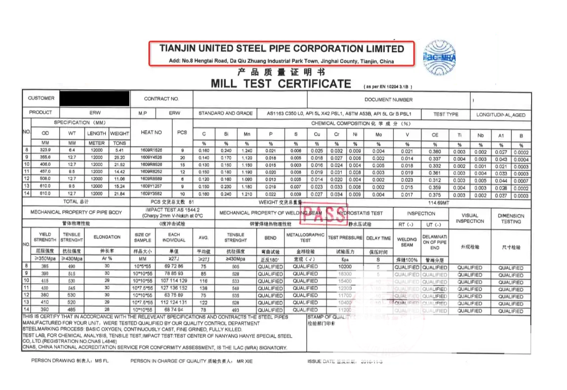
Even if you don’t find anything unusual in the above steps, it doesn’t mean your supplier is qualified. I suggest you check its MTC in the next step. I know an MTC is easy to be “cloned”, but you may still find some weak points in it.
1) The company name – as you can see in the above picture, the name is very similar to our company name, but they are absolutely different. On a real certificate, the “Co.” would never be written as “Company”, and the “Ltd” would never be written as “Limited”.
2) The CNAS certification – CNAS is an organization that evaluates whether a lab can be accredited to National Accredited Testing Laboratory in China. It has bilateral or multi-lateral accreditation cooperation agreements with relevant accreditation organizations around the world. So we can check this certificate also to eliminate our doubts. First, go to the CNAS official website; Second, click on “Find an Accredited Body”; Then, choose “Testing & Calibration Laboratories”, and type in the registration number or the company name; Finally, you can check if the registration number and company name are matched to the MTC you have;
3) The API certification number – Usually, a line pipe mill that is holding the API certification would show the certification numbers on the MTC. While there is none of it on the sample MTC above.